Optical Switching Technologies in All-Optical Communication
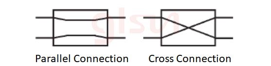
Optical Switch (OS) is a device with one or more selectable transmission windows that can perform mutual conversion or logical operations on optical signals in an optical transmission line or integrated optical path. The basic form of an optical switch is 2x2: that is, there are two optical fibers at each input and output, and two connection states can be completed: parallel connection and cross connection, as shown in Figure 1. Larger space-division optical switching units can be composed of cascaded and combined basic 2x2 optical switches and corresponding 1x2 optical switch stages.

Optical switches play a crucial role in optical networks. In Wavelength Division Multiplexing (WDM) transmission systems, optical switches can be used for wavelength adaptation, regeneration, and clock extraction. In Optical Time Division Multiplexing (OTDM) systems, optical switches can be used for demultiplexing. In all-optical switching systems, optical switches are key components of Optical Cross-connects (OXC) and are also important devices for wavelength conversion. Based on the number of input and output ports, optical switches can be classified into various types such as 1x1, 1x2, 1xN, 2x2, 2xN, MxN, etc., each having different applications in various scenarios. Their application range mainly includes protection switching systems in optical networks, optical source control in fiber testing, real-time monitoring systems for network performance, testing of optical devices, the switching core of OXC equipment, optical add/drop multiplexing, optical testing, and optical sensing systems.
Mechanical Optical Switches
Currently, the most widely used types are the traditional 1x2 and 2x2 mechanical optical switches. Mechanical optical switches can directly couple light to the output end by moving optical fibers. They use prisms or mirrors to switch the light path, directing or reflecting light to the output end.
Three main types of mechanical optical switches:
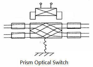
Prism-based optical path switching: The basic structure of a prism-based optical path switching optical switch is shown in Figure 2. The optical fiber is connected to a collimating lens (collimator) and is fixed in place. The optical path between the input and output ports is changed by moving the prism.
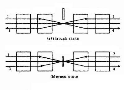
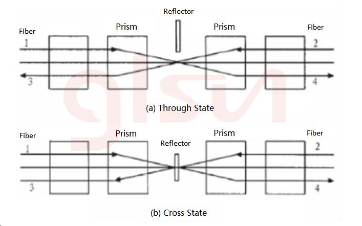
Mirror-based switching: The working principle of a mirror-based optical switch is shown in Figure 3. When the mirror is not in the optical path, the optical switch is in the straight-through state, and the light entering optical fiber 1 enters optical fiber 4, and the light entering optical fiber 2 enters optical fiber 3. When the mirror is at the intersection of the two beams, the optical switch is in the cross state, and the light entering optical fiber 1 enters optical fiber 3, and the light entering optical fiber 2 enters optical fiber 4 to switch the optical path.
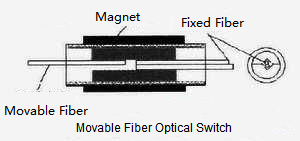
Movable fiber optical switch: Shown in Figure 4, fixes one end of the optical fiber while the other end is moved to couple with different ports of the fixed fiber, thus achieving light path switching.
The advantages of mechanical optical switches include low insertion loss (<1 dB), high isolation (>45 dB), and insensitivity to wavelength and polarization. The manufacturing technology for these switches is well-established. However, they have several drawbacks: the switching time is relatively long (on the order of milliseconds), they are bulky, and it is challenging to create large-scale optical switch matrices with them. Additionally, there can be issues with back bounce, jitter, and poor repeatability. While mechanical optical switches have seen widespread use in recent years, as optical network scales continue to expand, these switches are increasingly unable to meet the demands of future high-speed, large-capacity optical transport networks.
MEMS Optical Switch
In recent years, micro-electro-mechanical optical switches have developed rapidly. These switches combine semiconductor microfabrication technology with micro-optics and micro-mechanics, resulting in a new type of integrated micro-electro-optical switch. They represent the mainstream direction for the development of large-capacity switching in optical networks.MEMS (Micro Electro-Mechanical System) optical switches are made by etching several tiny mirrors onto a silicon wafer. These movable micromirrors can rise, rotate, or move under the influence of electrostatic or electromagnetic forces, thereby changing the propagation direction of the input light to achieve the function of switching optical paths.
MEMS optical switches have significant advantages over other types of optical switches: the switching time is generally on the order of a few milliseconds; they use IC manufacturing technology, making them small in size and highly integrated; and their operation is independent of the format, protocol, wavelength, transmission direction, polarization direction, or modulation mode of the optical signal, allowing them to handle optical signals of any wavelength. Additionally, they combine the low insertion loss, low crosstalk, low polarization sensitivity, and high extinction ratio of mechanical optical switches with the high switching speed, small size, and ease of large-scale integration of waveguide switches.
Based on functional implementation methods, MEMS optical switches can be divided into light path blocking type, movable fiber docking type, and micromirror reflection type. Micromirror reflection type MEMS optical switches are convenient for integration and control, making them suitable for forming optical switch arrays. These switches are a key focus of MEMS optical switch research and can be further classified into two-dimensional (2D) MEMS optical switches and three-dimensional (3D) MEMS optical switches. The concept of one-dimensional (1D) MEMS optical switches has also been proposed.
The so-called 2D MEMS optical switch refers to a configuration where the movable micromirrors and optical fibers are located in the same plane, and each movable micromirror is either in an on-state or an off-state at any given time. In this setup, the movable micromirror array is connected to N input fibers and N output fibers. For an NxN optical switch matrix, the required number of movable micromirrors is N². Therefore, this method is also known as the N² configuration scheme. For example, a 4x4 2D optical switch has 16 movable micromirrors, and four 4x4 optical switches can be combined to form an 8x8 optical switch, which would contain 64 movable micromirrors.
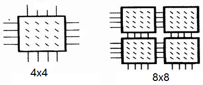
The mirror-based 2D MEMS devices consist of a two-dimensional micromirror array controlled by electrostatic forces and mounted on a mechanical base. The typical size is about 10 cm. A collimated beam and rotating micromirrors form a multi-port optical switch. The spatial fine-tuning rotating mirrors of the 2D MEMS are monolithically integrated on a silicon substrate using surface micromachining technology. The collimated light is directed to the appropriate output port by the proper rotation of the micromirrors. Micro hinges attach the micromirrors to the silicon substrate, with two push rods on either side of the micromirror. One end of the push rod is connected to the hinge point of the micromirror, and the other end is connected to the hinge point of a translating disk. The switching state is adjusted by the SDA (Scratch Drive Actuator) regulator, which adjusts the translating disk to rotate the micromirror. When the micromirror is horizontal, it allows the light beam to pass through it. When the micromirror rotates to a position perpendicular to the silicon substrate, it reflects the incident light beam onto its surface, directing the light beam to the corresponding output port of the micromirror.
The working principle of a three-dimensional Micro Electro-Mechanical Systems (MEMS) optical switch is illustrated in Figure 7, which shows the optical path diagram of a 4x4 optical switch. The primary advantage of this configuration is its simplicity in control. The main component of the control system is a transistor-transistor logic (TTL) driver, supplemented by a level-shifting circuit. This setup can provide the necessary voltage levels for each micromirror to function properly.
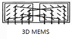
In three-dimensional MEMS optical switches, the mirrors can deflect in any direction. These arrays typically appear in pairs: the input light beam reflects off the mirrors in the first array to the mirrors in the second array, and then the light is directed to the output port. The position of the mirrors must be controlled with extreme precision, achieving an accuracy of up to one-millionth of a degree. Three-dimensional MEMS arrays could be the right choice for large-scale cross-connects, especially when wavelength bands are switched from one fiber to another.
Three-dimensional MEMS optical switches primarily use two N-mirror arrays to connect the light paths between two fiber arrays, with each micromirror having multiple possible positions. Since MEMS optical switches rely on mirror rotation to achieve switching, any mechanical friction, wear, or vibration could potentially damage the optical switch.
Although two-dimensional and three-dimensional MEMS optical switches have already been commercialized, they still face several challenges. The manufacturing process for MEMS, which involves micromirrors, must meet high precision requirements. The integrity of the structure and the flexibility of the micromirrors' rotation must be maintained even after millions or tens of millions of switch cycles to ensure the stability and continuity of optical network information transmission. MEMS optical switches must also meet mass production requirements, which demands high process stability. Additionally, the packaging and automated installation processes for MEMS, as they interact with end users, are crucial considerations.
Despite these challenges, MEMS optical switches are preferred because they combine the low loss, low crosstalk, polarization insensitivity, and high extinction ratio of conventional mechanical optical switches with the fast switching speed, compact size, and ease of large-scale integration of waveguide switches. For future backbone optical networks or large-capacity service switching applications, solutions based on MEMS optical switch technology have become a mainstream choice.
Technical Assessment Indicators of Optical Switches
The performance of optical switches is determined by factors such as traffic volume, operating conditions, and environmental factors. The requirements for optical switches are: on one hand, they must exhibit good performance in terms of insertion loss, crosstalk, extinction ratio, switching speed, switching scale, and switch size; on the other hand, they must be capable of being integrated into large-scale switch arrays to meet the demands of modern networks.
Optical switches are generally uated using the following key parameters:
Size: The size of the switching matrix reflects the switching capacity of the optical switch. The requirements for the switching matrix size vary depending on the network position of the optical switch. With the rapid growth in communication demands, the switching capacity of optical switches needs to be significantly increased, such as having more than 1000x1000 switching capacity in backbone networks. For large switching capacities, multiple smaller optical switches can be combined to form a larger switch.
Switching Speed: Switching speed is a crucial performance metric for optical switches. There are two important time scales for switching speed. When the switching time from one port to another reaches several milliseconds, it is usually sufficient for rerouting due to failures. For synchronous digital hierarchy (SDH) / synchronous optical network (SONET), a switching time of 50 milliseconds is nearly imperceptible at the upper layers when rerouting due to failures. When switching time reaches the nanosecond range, it can support packet switching in optical Internet. This is crucial for achieving the functionality of the optical Internet.
Loss: When optical signals pass through an optical switch, energy loss is inevitable. The impact of optical switches and their cascades on network performance is significant when designing the network based on power budgets. Loss and interference affect power budgeting. There are primarily two causes of optical switch loss: loss due to coupling between optical fibers and optical switch ports, and loss due to the optical switch material itself. Generally, optical switches using free-space switching have lower loss compared to those using waveguide switching. For example, liquid crystal and MEMS optical switches typically have lower loss, around 1 to 2 dB. In contrast, lithium niobate and solid-state optical switches have higher loss, approximately 4 dB. Loss characteristics affect the cascading of optical switches and limit their scalability.
Switching Granularity: Different optical network services have varying demands for switching and granularity used within the optical domain. Switching granularity can be categorized into three types: wavelength switching, wavelength group switching, and fiber switching. Switching granularity reflects the flexibility of the optical switch in handling services. This is crucial for accommodating various network service needs, as well as for network protection and restoration.
Blocking Characteristics: Blocking characteristics refer to the ability of an optical switch to route any input signal to any output port at any given time. The blocking characteristics become more pronounced in large or cascaded optical switches. Optical switches are required to have strict non-blocking characteristics.
Scalability: The scalability of optical switches varies based on different principles and technologies. Some technologies allow operators to increase the switch capacity as needed. Many switch structures can be easily upgraded to 8x8 or 32x32 configurations but may not scale to hundreds or thousands of ports, limiting their use to constructing OADMs (Optical Add-Drop Multiplexers) or OXCs (Optical Cross-Connects) for metropolitan networks rather than backbone networks.
Reliability: Optical switches need to exhibit good stability and reliability. In certain extreme cases, optical switches may need to perform thousands or even tens of thousands of frequent operations. In some scenarios, such as protection switching, the number of switch operations may be minimal, and maintaining the state of the optical switch becomes more crucial. For instance, with inkjet bubble optical switches, maintaining the bubble state is an important consideration.
Many factors influence the performance of optical switches, including crosstalk between switches, isolation, and extinction ratio, all of which are critical to network performance. When optical switches are cascaded, these parameters significantly impact the network's performance. Optical switches are required to be transparent to rate and service types. When constructing absolutely non-blocking large optical switch matrices, reducing crosstalk, minimizing loss, and achieving low cost are key research areas.
Optical switch technology is rapidly evolving, with several trends worth noting. As traffic demands surge, the switching capacity of backbone networks also increases, necessitating the continuous expansion of optical switch matrix sizes. Additionally, the explosive growth of IP services requires future optical transport networks to support optical packet switching, and future core routers will need to perform switching at the optical layer. This places higher demands on the switching speed of optical switches (in the nanosecond range).
Thermo-optic switch arrays and micro-mechanical switch arrays, due to their high level of integration, are expected to be the direction for large-scale array optical switches. MEMS optical switches currently show the most promise and are best suited to meet the requirements of DWDM (Dense Wavelength Division Multiplexing) all-optical communication networks. With the advantages of strong compatibility, ease of integration, design flexibility, and large-scale production capabilities, the integration and industrialization of MEMS optical switches will be a key focus for their future development. Traditional mechanical optical switches have substantial market potential in optical signal monitoring applications. In summary, high-capacity, high-speed, transparent, and low-loss optical switches will play increasingly important roles in the development of optical networks.
Powering High-Density Data Center Connections
The modern data center is a demanding environment. It craves speed, efficiency, and scalability, all while navigating the constraints of physical space. Enter MPO fiber optic cables, a critical innovation that addresses these challenges, making them the backbone of high-density data center connectivity. MPO (Multi-Fiber Push-On) fiber optic cables are a key technology for high-density, high-bandwidth applications in data centers. They offer a faster, more efficient way to connect network devices compared to traditional single-fiber or duplex fiber optic cables.
What are MPO Cables?
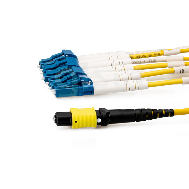
MPO stands for "Multi-Fiber Push On." These cables house multiple optical fibers within a single connector, enabling a significant increase in data transmission capacity compared to traditional single-fiber cables. Imagine it as a multi-lane highway versus a single country road; more lanes equate to more traffic flow and faster speeds. MPO cables contain multiple optical fibers (typically 8, 12, or 24) pre-terminated with a specialized connector. This connector allows for quick and easy installation, unlike traditional fiber cables that require manual termination on-site. MPO connectors are also known by the trademarked term MTP (MPO connector from US Conec), though both terms are often used interchangeably.
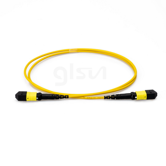
Benefits of MPO cables in the Data Center
High Density: MPO cables excel in maximizing space. Their compact design allows for more connections within a smaller footprint, crucial for the ever-growing equipment density in data centers. This translates to efficient utilization of valuable rack space and improved cable management. MPO cables pack a much higher fiber count into a single connector compared to duplex cables. This reduces cable clutter and saves space in data centers.
Scalability: As data demands grow, MPO cables provide the flexibility to easily scale up connectivity. Adding new connections is as simple as plugging in another MPO cable, ensuring your infrastructure can adapt to evolving needs without major overhauls. MPO cables can handle significantly more data traffic compared to duplex cables.
Speed and Bandwidth: MPO cables support high-speed data transmission, catering to the bandwidth-hungry applications of modern data centers. They are ideal for 40G, 100G, and even 400G Ethernet connections, ensuring your data center remains at the cutting edge of performance.
Faster Deployment: MPO cables come pre-terminated, meaning they are ready to plug and play. MPO cables simplify cable management and reduce the number of connections needed. This significantly reduces installation time and complexity compared to traditional fiber optic cables that require on-site termination, leading to faster deployment and reduced downtime. Pre-terminated MPO cables eliminate the need for field termination, saving time and labor costs during installation.
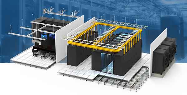
Common MPO Configurations in Data Centers
Trunk Cables:These connect different areas within the data center, like between server racks and patch panels, carrying a high volume of data traffic.
Harness Cables/Fanouts: These break out an MPO connector into several individual connectors, facilitating connection to individual equipment ports.
Cassette Modules: These offer a modular solution for patching and managing MPO connections within a compact housing, improving organization and accessibility.
Choosing the Right MPO Cable, several factors need to be considered when choosing MPO cables, including:
Fiber Count: The number of fibers in the cable will determine its bandwidth capacity.
Cable Length: MPO cables are available in various lengths to suit different data center layouts.
Connector Type: MPO connectors come in different polish types (PC, UPC, and APC) for single-mode or multimode fiber applications.
Polarity: Ensuring correct polarity is essential for proper data transmission. MPO cables come in different polarity types, and it's crucial to choose and configure them appropriately.
Testing and Cleaning: Due to their high density, MPO connectors require specific cleaning tools and testing methods to maintain optimal performance.
As data centers continue to evolve and demand ever-increasing capacity, MPO fiber optic cables will remain a critical technology. Their ability to deliver high-density, scalable, fast deployment and high-speed connections makes them the ideal solution for supporting the ever-growing bandwidth demands of modern data centers. MPO fiber optic cables are a powerful solution for high-speed data center networks. If you're planning a data center upgrade, MPO cables are definitely worth considering.
MEMS Optical Cross Connect Switch (OXC)
Optical cross-connect switch (OXC) is a matrix optical switch with NxN ports. It can be used to build a CDC ROADM system (colorless, directionless, contentionless reconfigurable optical add/drop multiplexer).
OXC can be built with a 1xN port optical switch. In order to build NxN port OXC module, it needs 2N 1xN port optical switches. The size and cost of the OXC module increase dramatically when the number of port increases, so the port number of this OXC is usually limited to 32x32 ports.
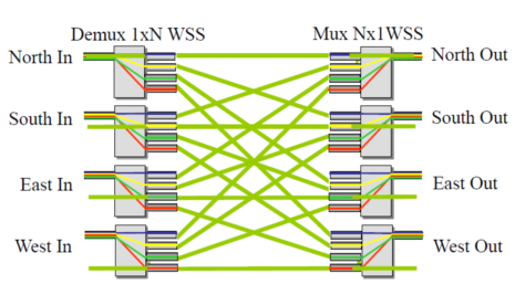
4x4 OXC module built with 8 1x4 switches
2D MEMS optical switch
The second technical solution to realize OXC is a Cross-Bar optical switch based on a MEMS mirror array. It has 2 input ports and 2 output ports. The optical path switching is achieved through 4 MEMS mirrors. Every mirror has two states, lying horizontally on the substrate to allow the beam to pass through (OFF) or standing upright on the substrate to reflect the beam (ON).
SEM photos of the MEMS chip and a single mirror, as well as MEMS torsion mirror. The mirror is supported by a polysilicon beam. When there is no voltage applied to the electrode, the mirror remains horizontally. When powered on, the mirror stands upright on the substrate driven by electrostatic force.
Matrix optical switches based on 2D MEMS technology require a NxN scale mirror array to make a NxN optical switch. All optical paths of the device are in one plane, that is why it is called a 2D MEMS optical switch.
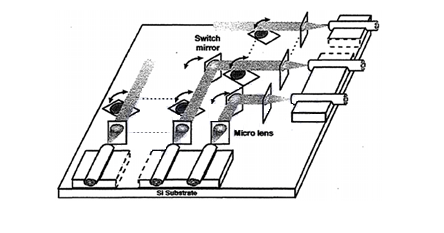
First Generation 2D MEMS matrix switch
The switching of the optical path is achieved through a mirror. The mirror is hinged on the base. One end of the two pull rods is connected to the mirror, and the other end is connected to a translation stage. The translation stage is driven by a scraper-type actuator to pull the mirror forward. The mirrors rotates as they are pulled.
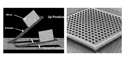
2D MEMS Mirror Array
Matrix optical switches based on 2D MEMS mirror arrays have the advantages of simple structure and easy packaging, but their scalability is limited. For different port link relationships, the optical path lengths vary greatly, which will introduce coupling losses and loss uniformity. The tolerance for the optical path difference depends on the beam size in the free-space optical structure. According to equation (1), the smaller the spot ω0 is, the more divergent it is. According to equation (2), the shorter the collimation distance is.
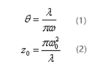
The coupling situation between two single-mode fiber SMFs increases sharply as the spacing between the fiber end faces increases. The spacing between two single-mode fibers is usually limited to <20μm. To increase fiber spacing to allow the placement of various free space optical components, thermal expanded core (TEC) fibers or lens fibers are usually used. Both TEC fiber and lens fiber can expand the spot size to be suitable for free space light transmission. The distance between two TEC fibers can be up to 10mm, while the distance between two lens fibers can be up to 50mm. For applications that require longer free space optical paths, collimating lenses are often required.
Applying TEC fiber or lens fiber to 2D MEMS optical switches helps to increase the free space optical path length to accommodate more MEMS mirrors and expand the optical switch port. However, the maximum allowed spot size is limited by the size of the mirror, which depends on the MEMS design and process. Mirror diameterФ>3ω0 is usually required to reflect more than 99% of the optical power. Therefore, the maximum port number of 2D MEMS optical switches is usually limited to 32×32.
OXC based on 3D MEMS technology
In order to further develop OXC system, 3D MEMS optical switches were developed. The basic structure of 3D MEMS OXC includes two MEMS mirror arrays and two two-dimensional fiber collimator arrays. Each input fiber collimator corresponds to a mirror in the first MEMS chip, and each output fiber collimator The straightener corresponds to a mirror in the second MEMS chip. All mirrors on the MEMS chip can deflect in two axes.
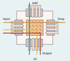
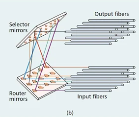
The beam from each input port is independently controlled by a mirror on the first MEMS chip and directed through biaxial deflection to another mirror on the second MEMS chip (corresponds to the output port). A mirror adjusts the direction of the reflected beam to point to the output through biaxial deflection. Therefore, through the control of two MEMS chips, optical signals can be exchanged from any input port to any output.
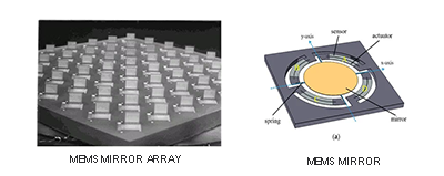
The OXC developed by Bell Labs includes two MEMS mirror arrays, two 2D fiber arrays and a Fourier lens. Each input-output link is built through a mirror on the first MEMS chip and another mirror in the second MEMS chip.
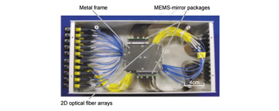
The new generation 3D MEMS OXC from NTT Lab replaces Fourier lenses with a circular concave reflector. The use of a circular concave mirror can reduce the off axis aberration of the edge port to reduce insertion loss.

What’s a Fiber Optic Switch?
Fiber Optic Switch is a device with one or more selected transmission windows that can perform mutual conversion or logical operation on optical signals in optical transmission lines or integrated optical circuits. The basic form of optical switch is 2x2, that is, every input port and output port have two optical fibers, which can complete two connection states, parallel connection and cross connection. The large space optical switch unit can be composed of the combination of a basic 2x2 and 1x2 fiber optic switch.
Optical switches play an important role in optical networks. In Wavelength Division Multiplexing (WDM) transmission systems, optical switches can be used for wavelength driving, regeneration and clock extraction. In Optical Time Division Multiplex (OTDM) system, optical switches can be used for demultiplexing; in all-optical switching systems, optical switches are key components of Optical Cross-connect (OXC), and are also important components for wavelength conversion. The number of input and output ports of the switch can be divided into 1×1, 1×2, 1×N, 2×2, 2×N, M×N, etc. They have different uses in different occasions. They can be widely used in protection switching system of optical network, light source control in optical fiber testing, real-time monitoring system of network performance, testing of optical devices, construction of switching core of OXC equipment, optical add/drop multiplexing, optical testing, optical Sensing systems, etc.
Main Types of Fiber Optic Switches
At present, the most widely used ones are still 1×2 and 2×2 mechanical optical switches. Traditional opto-mechanical optic switches can directly couple light to the output end through moving optical fibers, use prisms and reflectors to switch light paths, and send or reflect light directly to the output end.
There are three main types of mechanical optical switches: one uses prism switching light path technology, the other uses mirror switching technology, and the third uses moving optical fiber to switch the light path. The optical fiber is connected to the lens (collimator) that plays a collimating role and is fixed. The optical path between the input and port output is changed by moving the prism. When the reflector does not enter the light path, the optical switch is in a straight-through state. The light entering from fiber 1 enters fiber 4, and the light entering from fiber 2 enters fiber 3. When the reflector is at the intersection of the two light rays, the optical switch is in the intersection state. , the light entering fiber 1 enters fiber 3, and the light entering fiber 2 enters fiber 4 to achieve optical path switching. The mobile optical fiber optical switch is an optical fiber with fixed ends. The device at the other end of the mobile device is connected to different ports of the fixed device to realize switching of optical paths. This type of optical switch has low return loss and is greatly affected by ambient temperature. There is no real switching product.
The advantages of mechanical optical switches are low insertion loss (<1dB), high isolation (>45dB), independent of wavelength and detour, and mature production technology. Faced with the total switching action time (ms), the size is relatively large, and it is not suitable for large-scale foreign optical switch matrices, and sometimes there are problems of rebound and poor repeatability. Mechanical optical switches have been widely used in recent years. However, as the scale of optical networks continues to expand, this type of switch is difficult to adapt to the future development needs of high-speed and large-capacity optical transmission networks.
Micro-electro-mechanical System (MEMS) Optical Switches
Microelectronic mechanical optical switches have developed rapidly in recent years. They are a new type of micro-electro-optical integrated switch produced by combining semiconductor micro-processing technology with micro-optical and micro-mechanical technologies. It is a new type of switch for large-capacity switching optical networks. The mainstream direction of switch development.
MEMS(Micro Electro-Mechanical System) optical switches are carved into a number of tiny lenses on a silicon crystal. Through the action of electrostatic force or electromagnetic force, the movable mirrors can be raised, lowered, rotated or moved, thereby changing the propagation direction of the input light to realize the function of optical path on/off. MEMS optical switches have obvious advantages over other optical switches. The switching time is measured in microseconds. MEMS fiber optic switch adopts IC manufacturing technology, is small in size and highly integrated. The working method has nothing with the format, protocol, wavelength, transmission direction, matrix direction, and modulation of the optical signal. It can process optical signals of any wavelength. Besides, it has the advantages of low insertion loss, low crosstalk, low polarization sensitivity, high extinction ratio, high switching speed, small size, and easy large-scale integration.
According to functions, MEMS optical switches can be divided into optical path bias type, moving fiber contact type and mirror reflection type. Mirror reflection type MEMS optical switches are easy to integrate and control, and can easily form an optical switch array. They are the focus of MEMS optical switch research. They can be divided into 2D MEMS optical switches and 3D MEMS optical switches. The concept of 1D MEMS fiber optic switches is also proposed. The so-called 2D means that the movable mirror and fiber are located on the same plane, and the mirror is either on or off at any specified moment. In this mode, the mirror array is connected to N input fibers and M output fibers. The number of mirrors required for an N×N matrix optical switch is N². Therefore this method is also called N² structure scheme.
Optical Transceiver Module Industry Chain
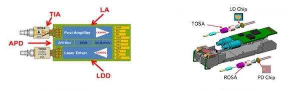
Optical transceiver module consists of transmitting unit, transmission unit and receiving unit. The transmitting unit inputs an electrical signal of a certain power. After being processed by the internal driver chip, the driving laser or light-emitting diode emits a modulated optical signal of corresponding power and transmits it through the optical fiber. The receiving end converts the optical signal into an electrical signal by a light detection diode, and output an electrical signal of corresponding power after passing through the pre-amplifier.
The upstream of the optical transceiver module industry includes optical chips, optical devices, electrical chips, etc. The downstream of the optical transceiver module industry mainly includes telecom operators, Internet and cloud computing companies, etc. The application fields of optical transceiver module products cover industries such as Internet services and the telecom market.
The optical transceiver module follows the packaging sequence of chip-assembly (OSA)-module. The laser chip and detector chip are formed into TOSA and ROSA through traditional TO packaging. At the same time, the supporting electrical chip is mounted on the PCB, and then the optical channel and optical fiber are connected through precision coupling, and finally packaged into a complete optical transceiver module. The emerging COB, which is mainly used in short-distance multi-mode, uses a hybrid integration method. The chip is mounted on the PCB through a special bonding and welding process and uses non-hermetic packaging. The upstream of optical transceiver modules is mainly optical chips and passive optical devices, and the downstream customers are mainly telecom main equipment manufacturers, operators and Internet & cloud computing companies. Therefore, optical transceiver modules have a broad and growing market space.
Optical transceiver modules can be divided into QSFP, QSFP28, CFP, CFP2, CFP4, CXP, SFP, CSFP, SFP+, GBIC, XFP, XENPAK, X2, SFF and other types according to the packaging method. Among them, SFP and QSFP have the advantages of high performance and low power consumption, and have become products currently used on a large scale.
Optical transceiver module rates can be divided into 1Gbps, 2.5Gbps, 10Gbps, 25Gbps, 40Gbps, 50Gbps, 100Gbps, 200Gbps, 400Gbps, 800Gbps, etc. According to market stratification by speed, low-speed optical transceiver modules have the greatest demand and can be used for broadband users, servers, and enterprise network access; higher-speed optical transceiver modules have smaller demand and are mainly used for long-distance communications by operators and data centers. The current growing demand for 100G/400G high data rate optical transceiver modules will synergistically drive the growth of the QSFP, QSFP-DD, and OSFP optical transceiver module markets.
According to the fiber access type, optical transceiver modules can be divided into single-mode optical transceiver modules and multi-mode optical transceiver modules. The transmission distance of multi-mode optical transceiver modules is shorter, usually between 500 meters and 2,000 meters, while the transmission distance of single-mode optical transceiver modules is longer, usually between 10 kilometers and 160 kilometers.
With the rapid development of the information technology industry and the rapid growth of data traffic, the performance index requirements for optical transceiver modules are getting higher and higher. Data rate, transmission distance, power consumption, and volume have become important considerations. At present, optoelectronic components are constantly improving in the direction of high speed, wide spectrum, small loss, low power consumption, high sensitivity, short delay, weak nonlinearity, high integration, small size, low price, and silicon photonics.
The current main application markets of optical transceiver modules include the data communication market, telecommunications market and emerging markets. The data communication market is the fastest growing market for optical transceiver modules. It has surpassed the telecommunications market to become the largest market and is the mainstream growth of the optical transceiver module industry in the future. The telecommunications market is the first market for optical transceiver modules. 5G construction will significantly boost the demand for optical transceiver modules for telecommunications. While emerging markets include consumer electronics, autonomous driving, industrial automation and other markets, which are the markets with the greatest potential for future development.
The downstream optical transceiver modules are mainly used in three major scenarios: telecommunications bearer network, access network, data center and Ethernet. Telecom bearer networks and access networks both belong to the telecom operator market. Wavelength division multiplexing (xWDM) optical transceiver modules are mainly used in medium and long-distance telecom bearer networks, and optical interconnects are mainly used in long-distance and long-distance backbone core networks. Capacity transmission, and the access network market is the "last mile" from operators to users, including fiber-to-the-home passive optical networks (FTTH PON), wireless fronthaul (Wireless) and other application scenarios. The data center and Ethernet market mainly includes data center internal interconnection, data center interconnection (DCI), enterprise Ethernet and other scenarios.
Telecommunications Market:Mainly used in base stations/PON/WDM/OTN/switches/routers and other equipment.
Data center market (data communications market):Main application servers/top-of-rack switches/core switches and other equipment.
OBP 光バイパス保護システムのアプリケーション
光ケーブル リソースによって制限される基地局の大規模かつ迅速な展開に伴い、基地局ネットワークがチェーン構造または大規模なリング構造を持つことが非常に一般的です。 このようなネットワーク構造では、ひとたびリンク切断や多点オープンループ事故が発生すると、広範囲にわたるサイト停止につながります。 このため、停電、伝送設備の故障、局アクセス困難等による大規模な局停止をいかに回避するかが喫緊の課題となっている。
光バイパス保護システムOBPは、基地局の送信装置の電力状態と発光状態をリアルタイムで監視することができ、停電や送信装置の故障による大規模な局停止を効果的に回避でき、信頼性が高いという利点があります。 、スイッチング速度が速く、コストが低いため、シンプルで効果的なソリューションです。
光バイパス保護技術の紹介
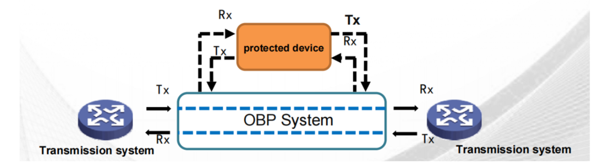
上図に示すように、光バイパス保護システムは、光ファイバ通信の分野で適用される光スイッチング システムの一種で、障害のあるネットワーク ノードを自動的にバイパスすることができ、ネットワーク ノードの電源状態と障害を自動的に識別できます。 光信号の出力状態を監視し、ローカルの光機器に障害(停電、ハードウェアまたはソフトウェアの障害など)が発生した場合には、即座にバイパス光パスに切り替え、通信回線がローカル機器をバイパスします(つまり、ローカル光機器の障害)。 、障害のあるノード)を使用して、障害のあるノードによって引き起こされる完全なブロッキング障害を回避し、システムの接続を確保します。
OBP は、保護対象機器の電源状態と保護対象機器の光パワーの両方をリアルタイムで検出できる内蔵の双安定光スイッチによってメインおよびバックアップ ルートの切り替えを完了します。動作原理は次のとおりです。
(1) 保護対象機器に電力が供給され、正常に放射されている場合、光路は正常な状態にあります。
(2) 保護された機器の電源がオフで、光パワーが事前に設定されたしきい値より低いことが検出されると、OBP は自動的にファイバーパススルー状態に切り替わります。
(3) OBP デバイスのみの電源がオフで、保護されるデバイスが正常に動作している場合、OBP は内部の高安定コンデンサの助けを借りて、保護されるデバイスの光パワーを即座に検出します。 光パワーが正常であれば、切り替え動作は行われません。
結論
OBP 装置の光パワー検出は正確で、挿入損失は小さいです。 基地局の停電時には即座にバイパス状態に切り替わり、ローカル伝送装置をバイパスすることができます。 基地局の電源が回復すると、伝送装置が完全に起動した後、即座にメイン モードにカットバックでき、バイパスおよびカットバックでネットワーク上の他のネットワーク要素が正常に動作することを保証します。 OBP 装置の保護機能を備えているため、リンクが多すぎる場合や障害が頻繁に発生する基地局に大量に適用できるため、リンクが多すぎる場合や障害が頻繁に発生する多数の基地局で使用することができます。 サービスの正常な運用を適切に保護するために、メンテナンスのために基地局に入ることが困難な場所。
What's the Differences Between Single Mode and Multimode Fiber?
Technical Difference
Core Diameter
Single-mode fiber has a small core diameter (8.3 to 10 microns), allowing only one mode of light to propagate. Multimode fiber optic cables have large diameter cores (50 to 100 microns) that allow multiple modes of light to propagate.
Light Source
Multimode devices typically use LEDs or lasers as the light source, while singlemode devices use lasers or laser diodes to generate the light injected into the cable.
Main Differences
Distance
Light travels longer in single-mode cables than in multimode cables, so multimode fiber is suitable for short-distance applications, up to about 550m at 10Git/s. When the distance exceeds 550m, single-mode fiber is preferred.
Price
Multimode fiber usually costs less than singlemode fiber.
Bandwidth
Singlemode has higher bandwidth than multimode, up to 100,000 GHz.
Multimode Fiber Connector Types
The types of multimode fiber optic connectors in circulation include ST, SC, FC, LC, MU, E2000, MTRJ, SMA, DIN, and MTP&MPO, etc. The most commonly used types of fiber optic connectors include ST, SC, FC, and LC.
|
MMF Connector |
Ferrule Size |
Typical Insertion Loss (dB) |
Application Features |
|
SC |
φ2.5mm ceramic |
0.25-0.5 |
Mainstream, reliable, fast deployment, filed fit |
|
LC |
φ1.25mm ceramic |
0.25-0.5 |
High density, cost-effective,filed fit |
|
FC |
φ2.5mm ceramic |
0.25-0.5 |
High precision, vibration environment, field fit |
|
ST |
φ2.5mm ceramic |
0.25-0.5 |
Military, filed fit |
What are the advantages of multimode fiber?
While single-mode fiber patch cables offer advantages in terms of bandwidth and transmission distance, multimode fiber can easily support most of the distances required by enterprise and data center networks at a much lower cost than single-mode fiber. In addition, multimode fiber optic cables have many significant advantages.
Multi-user framework without lossy interference
The characteristic of multimode fiber is that it can carry multiple signals simultaneously in the same line, and most importantly, there is almost no loss of total power inside the signal.
Thus, a network user can send multiple data packets down the cable at the same time, and all information will be delivered to its destination without any interference and remain unchanged.
Support Multiple Protocols
Multimode fiber can support a variety of data transmission protocols, including Ethernet, Infiniband, and Internet Protocol. As a result, one can use the cable as a backbone for a range of high-value applications.
Cost-effective
With larger cores and good alignment tolerances, multimode fibers and components are less expensive, easier to use with other optical components such as fiber optic connectors and fiber optic adapters, and the operation, installation and maintenance of multimode patch cords Costs less than single-mode fiber optic cables.
Conclusion
Due to its high capacity and reliability, multimode fiber is commonly used in backbone applications in buildings, and in general, MMF cable remains the most cost-effective option for enterprise and data center applications up to a range of 500-600 meters.
But this is not to say that we can replace single-mode optical fiber with multi-mode optical cable. As for choosing single-mode optical fiber jumper or multi-mode jumper, it all depends on the application, transmission distance and coverage you need. Total budget allowed.